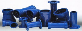
Cast Iron Flange Pipes
Cast Iron Flange Pipes
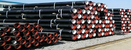
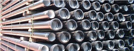
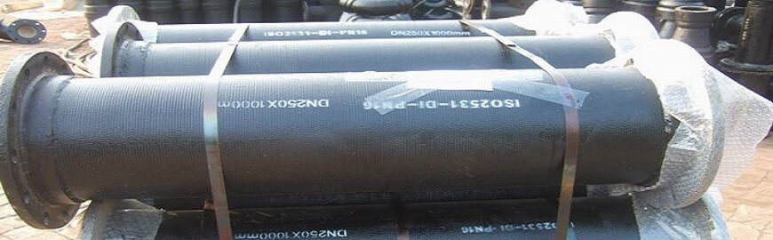
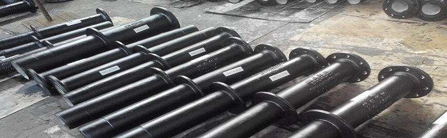
Cast Iron Flange Pipes as per IS: 1536 with Screwed on Flanges, Length : up to 5.5m, available in mix lengths and std lengths of 2.75, 3, 3.5, 4, 4.5, 5, 5.25 & 5.5m. The Pipes are generally supplied internally and externally coated with Bitumin.
The pipes are internally & externally coated with Bitumen paint. The flanges are generally supplied with flat face, however if required raised flanges may also be supplied. The flanges are generally drilled as per IS:1536 & IS:1538.
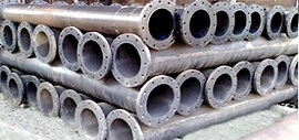
The spun pipes are casted centrifugally by De Lavaud process.
Size : 80 mm to 1000 mm
- Ash Disposal in Power Plants.
- Sand Stowing operations in Mines.
- Fire Fighting Systems.
- Sugar Industries for Spray pond, SO2 piping & Injection Piping.
- For Laying in Hilly Areas / Slopes, even exceeding the Angle of Repose.
- Treatment Plants-Portable Water, Effluent and Waste Treatment.
- Chemicals Industry application for cooler pipes for conducting various chemical fluids like Sulphuric Acid, Brines, Alkalies, etc.
- Cast Iron Double Flanged Pipes are widely used in Soda ASh Plants, Fertilizer Plants, Sulphuric Acid Plants.
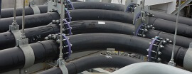
- Water Supply - Overhead Water Tanks, Pumping stations, Underground Mains, River Crossing, Hill Tracks, Sandy area, etc.
- Vertical Pipe Lines: for overhead Tanks / Elevated Service Reservoirs (EDR’;S).
- Disengagement Requirements:
- Application where pipelines are disengaged / dismantled for cleaning like in treatment plants for water, Effluent, Sewage and pump houses.
- Temporary installations, applications where pipelines are transferred. from one location to other: require Flange Pipes like temporary pipelines required for De-Watering mines or heavily inundated areas.
- Over Ground and & Exposed Installation: Flanged Pipes are most suitable for over ground pipelines like portions of Pipelines on Pillars / Pedestals for Rivers / Canal or Road crossing and bridges.
| Size DN (mm) | Pitch Circle Diameter (mm) |
D | E | b | a | f | Bolt size | No of Bolts | Bolt Length (mm) |
| 80 | 160 | 200 | 132 | 21.0 | 42 | 3 | 16 | 4 | 65 |
| 100 | 180 | 220 | 156 | 22.0 | 44 | 3 | 16 | 8 | 65 |
| 150 | 240 | 285 | 211 | 23.0 | 46 | 3 | 20 | 8 | 70 |
| 200 | 295 | 340 | 266 | 24.5 | 49 | 3 | 20 | 8 | 70 |
| 250 | 350 | 395 | 319 | 26.0 | 52 | 3 | 20 | 12 | 80 |
| 300 | 400 | 445 | 370 | 27.5 | 55 | 4 | 20 | 12 | 80 |
| 350 | 460 | 505 | 429 | 29.0 | 58 | 4 | 20 | 16 | 80 |
| 400 | 515 | 565 | 480 | 30.0 | 61 | 4 | 24 | 16 | 85 |
| 450 | 565 | 615 | 527 | 31.5 | 64 | 4 | 24 | 20 | 85 |
| 500 | 620 | 670 | 582 | 33.0 | 67 | 4 | 24 | 20 | 90 |
| 600 | 725 | 780 | 682 | 36.0 | 70 | 5 | 27 | 20 | 100 |
| 700 | 840 | 895 | 794 | 38.5 | 73 | 5 | 27 | 24 | 110 |
| 750 | 900 | 960 | 857 | 40 | 76 | 5 | 27 | 24 | 110 |
| 800 | 950 | 1015 | 901 | 41.5 | 79 | 5 | 30 | 24 | 110 |
| 900 | 1050 | 1115 | 1001 | 44.0 | 82 | 5 | 30 | 28 | 120 |
| 1000 | 1160 | 1230 | 1112 | 47.0 | 85 | 5 | 33 | 28 | 130 |
| CI Flange Pipe Mechanical Properties | |
| Ring test 80 to 300 DN | Modulus of rupture 390 (Min:) MPa |
| Tensile test 350 to 600 DN | Tensile strength 200 (Min:) MPa |
| Brinell Hardness test | Max. 230 BHN |
| CI Flange Pipe Hydrostatic Test Pressures(at works MPa) | ||
| Class | Upto 300 DN | 350 to 600 DN |
| LA | 2.5 | 1.6 |
| A | 2.5 | 1.6 |
| B | 2.5 | 1.6 |